GPS
Solar Tracker (3)
MTM
Scientific, Inc.
This series of webpages describes a GPS enabled
solar
tracker based upon the STMAX tilt-tilt platform design. The STMAX solar
tracker controller is
described in much more detail in our book "Build a Solar Tracker"
and at
http://www.mtmscientific.com/stmax.html.
The first webpage of this series described how to acquire time and
position data from a GPS module. The second webpage described how to
use
the GPS time and position data to calculate the position of the sun in
the sky. This webpage describes how to convert the aiming
position in azimuth and elevation to ADC units on the STMAX tilt-tilt
platform.
Calculating aim using a mathematical approach was found to be a very
difficult problem. Eventually we had the idea to measure various random
aiming
directions and see if there is a predictable correlation to
the tilt-tilt ADC counts for N/S and E/W. To our surprise there
indeed was a very good correlation for both, as shown in Figures 1 and
2.
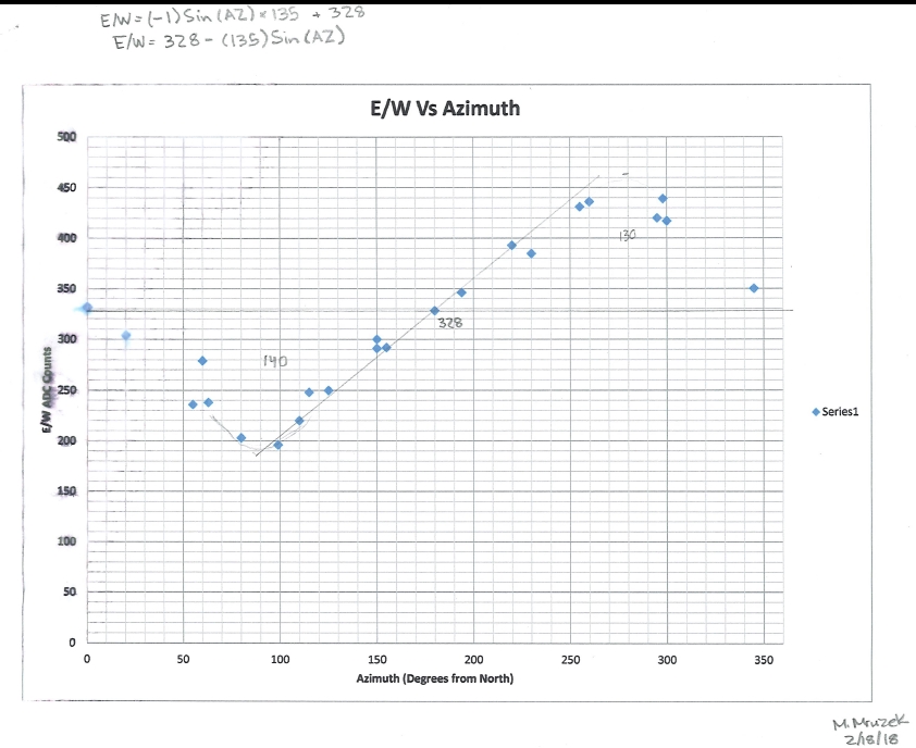 Figure 1. East and South
Correlation to ADC Counts
Figure 1. East and South
Correlation to ADC Counts
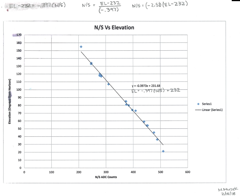 Figure 2. North and South
Correlation to ADC Counts
Figure 2. North and South
Correlation to ADC Counts
We were able to model both these correlations. The correlation formulas
are written on the graphs. We modeled the East/West correlation as a
sine
wave. We modeled the North/South correlation as a simple line
initially, however we later improved the correlation to be
trigonometric using N/S = 338 + 164*[COS(ELEVATION)]*COS(ABS(180-AZ)).
The trigonometric
correlation is more accurate. The concept of using ADC counts
from the MEMS accelerometer is explained in our book.
Here are the improved results in graphical form:
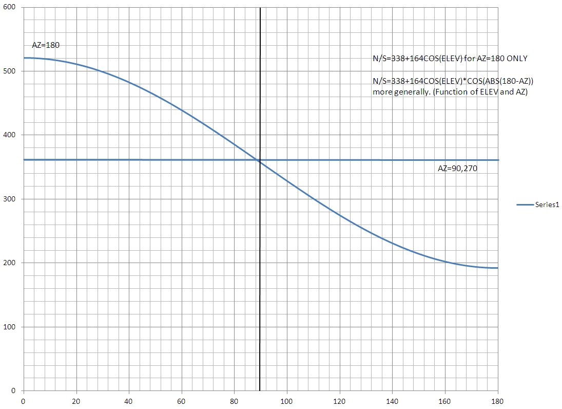
Figure
3. Improved North & South
Correlation related to ADC Counts
We used these correlations to calculate aiming directions in units of
ADC counts based upon the sun location calculated by the program
described previously.
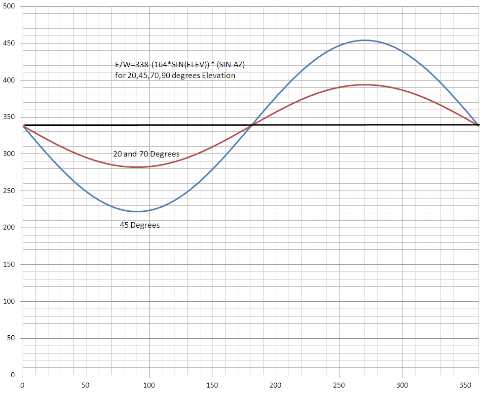
After using this
correlation to track the sun we found that there was significant
aiming error near the horizon. We did a more complete study of the
problem and discovered the amplitude of the sinusoid varies according
to the sine of the elevation. We show the correlation for 4 cases in
Figure 4. (Results are plotted for 20, 45, 70 and 90 degrees of
elevation). We see the sensitivity of the East & West aiming is
reduced as the tracker moves closer to the horizon. This is to be
expected based on the nature of the MEMS design. The constant in
the formula (338) is the ADC count when the tracker is level. The
coefficient of the SIN calculation is 1/2 the same level ADC count.
(Note: Both of these values vary slightly due to variance in the offset
and sensitivity of the particular MEMS sensor. )
Figure
4. Final North & South
Correlation to ADC Counts