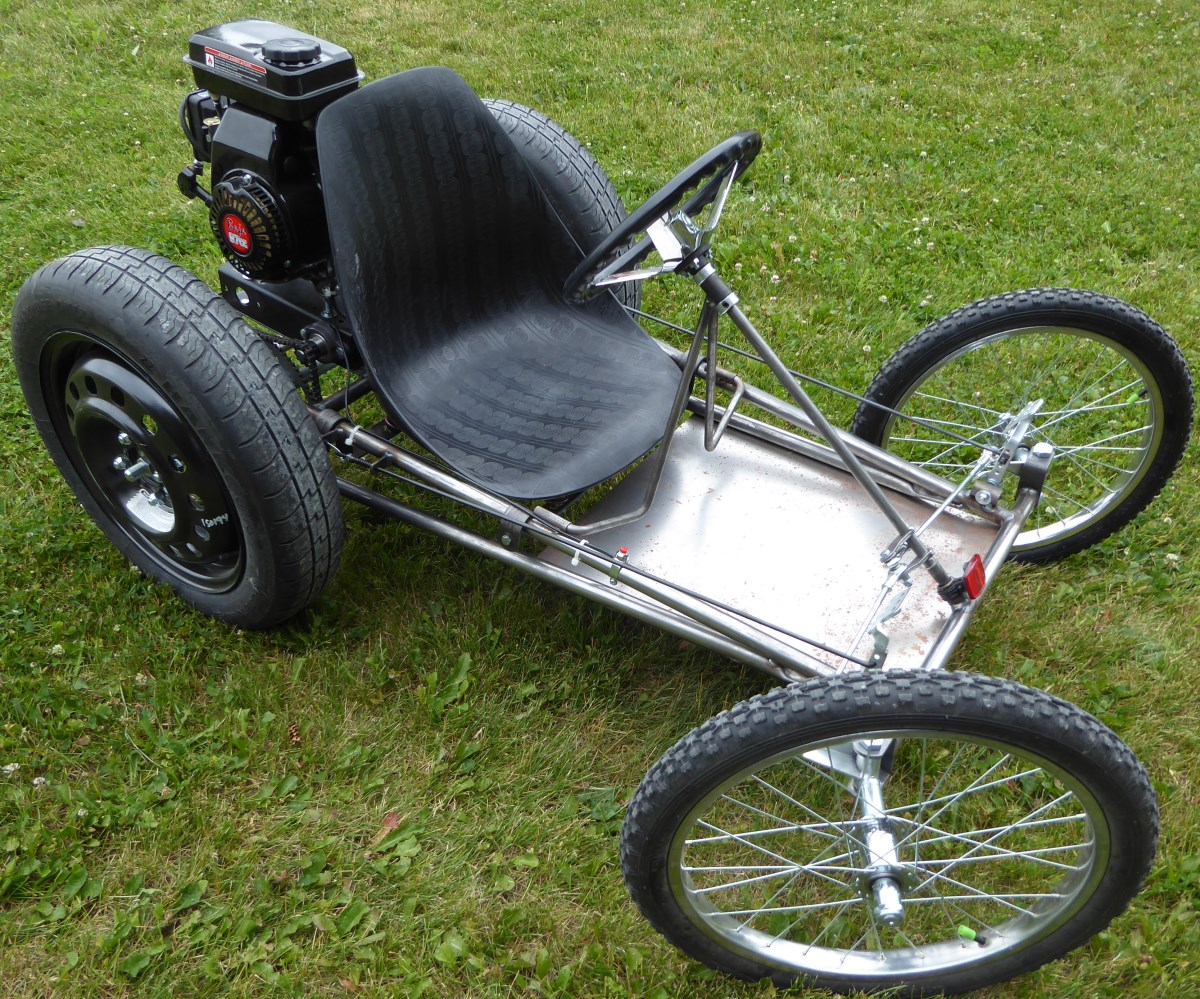
The Cyclecar
Project
MTM Scientific, Inc
The
Go-Kart Cyclecar Project was inspired by the Cyclecars of the
early automotive age. Many fine examples of Cyclecars were built by
amateurs between 1910 and 1930 with the desire to 'get on the road'
with a simple and
inexpensive vehicle. Cyclecars typically have
an air cooled engine, large wheels and a narrow-width profile. Many
Cyclecars had a single rear wheel to reduce expenses.
We endeavored to build a DIY Cyclecar using commonly available
off-the-shelf kit parts. This turned out to be surprisingly easy and
inexpensive to do. Many of the components are go-kart parts, with other
parts carefully selected from EBAY and other sources. For example, the
main frame of the
Cyclecar is a widely available and inexpensive go-kart frame from Azusa
Engineering.
Front
End & Steering
The
front end of the Cyclecar has large bicycle-type wheels
to raise the frame off the ground and provide good rolling resistance
to bumps and rough road. The front wheels are spoked with pneumatic
tires and ball bearings. The front wheels were originally designed for
use as part of a push-type garden cart. We found there were 2
primary issues with using these wheels and tires: The bearings were not
designed for high speed or rough service, and the pneumatic
inner
tubes
were prone to punctures and leaking.
Fortunately the issues with the ball bearings were easily and
inexpensively solved with a simple bearing replacement.
We were able to find replacement bearings of high quality which have
provided excellent service. The bearings we used are pre-packed with
grease and also sealed for protection from dirt and contaminants.
The issues with the pneumatic tires leaking were rather surprising to
us. We found that the fasteners for the spoke seats in the rims had
numerous
sharp edges. At first we tried to tape-over these sharp edges, but
that did not work for long, and the tires would start leaking again. We
eventually solved this
problem by replacing the original inner tubes with a special
'stop-leak' type.
This simple and inexpensive remedy has worked quite well for us.
Using large diameter tires on the front end required increasing the
width of the front
wheel base to elimate rubbing against the frame during sharp turns. We
incorporated 2 design features to solve this problem: We started by
choosing the largest and longest wheel spindles available. And, we used
shaft spacers to move the wheels outboard as much as possible. The
combination of these two design choices resulted in perfect placement
of
the front wheels, and provides the necessary turning clearance.
The steering linkage to the spindles is a more-or-less standard type of
ball end linkages.
We opted to weld our pinion arm to the steering wheel shaft
for
perfect
placement. We chose a butterfly type steering wheel to increase the
clearance underneath, which makes it much easier to enter and
exit the
driving seat.
Rear
End & Brakes
The
rear wheel shaft on the Cyclecar is a live axle. That
means the entire shaft rotates with the wheels. The rear axle is
supported by two ball bearings at opposite ends. We chose to use a
heavy duty 1.0 inch diameter shaft. The shaft has keyway cuts at both
ends. Both ends of the shaft are also stepped-down and threaded, which
is a great convenience for attaching the wheel hubs.
The rear shaft would have a tendency to drift right or left in the ball
bearing supports. We implemented a simple system of spacers to
precisely and rigidly position the shaft. The spacers are located at
opposite ends of the shaft. The spacers ride between the inner races of
the ball bearings and the outside wheel hubs. (The wheel hubs
are
solidly attached to the stepped-down shaft ends.) This simple system of
shaft spacers positions the live rear axle in a fixed location.
The rear wheels and tires of the Cyclecar are unusually large. The
large size was chosen to facilitate ground clearance and operation over
rough terrain. We searched extensively for suitable go-kart wheels, but
they were generally expensive and limited in size. The Cyclecar wheels
and tires are actually compact spares from a Ford Escort! We found
these wheels readily available on EBAY, at reasonable prices and in
like-new condition. The only modification we made to the wheels was to
drill a pattern of 4 mounting holes to match the hubs.
One of the most significant design choices for the Cyclecar was the
type of rear wheel drive. The rear shaft is a live axle. We initially
attached both rear wheels directly to the shaft to maximize traction.
Traction was indeed accomplished, but the steering was
difficult for anything more than a gradual turning radius. We
eventually progressed to using a single driven rear wheel drive. In
this
configuration the traction is still very good and the steering is
exceptionally easy and sharp. Since both the wheel hubs and shaft are
keyed, selecting the drive mode on a wheel is simply a matter of
including
a shaft key, or not. We have chosen to drive the wheel closest to the
engine, on the driver's right.
The Cyclecar uses a standard drum and shoe style go-kart braking
system. This approach to the brakes turned out to be ideal, since the
frame is designed for easy mounting of the components. The only
challenge with the brakes was securing their axial location on the rear
shaft. As supplied, the brakes are intended to be attached using a
shaft key and set screws on the driver's left. We found this method
worked at first, but eventually the set screws would loose their grip
and
components would began to move. We solved this problem by adding
special split-shaft collars on either side of the brake hub. The shaft
collars are
designed to securely grip the shaft, and they can be easily positioned
to any desired location along the shaft. By using shaft collars on both
sides of the brake hub, we also captured the shaft key inside
the
brake hub.
The Cyclecar uses a chain drive to transmit power from the engine to
the wheels. A large chain sprocket is attached to the rear axle. The
sprocket is also fixed to the shaft using a key. The position of the
sprocket on the shaft is fixed by using another pair of split shaft
collars,
identical to the method of locating the brake hub. The sprockets are
designed for standard Number 35 chain.
Engine &
Jackshaft
& Clutch
The
Cyclecar uses a 4 cycle internal combustion engine with
97cc displacement rated for 2.7 HP at 3600 RPM. We purposely chose to
use a small engine for overall economy, and focused on creating a drive
system with good mechanical advantage to effectively use the available
power. The big rear wheels and high RPM engine requires
a large ratio of speed reduction to develop good low speed
torque.
The large ratio of speed reduction from the engine to the wheels is
accomplished using a double reduction chain drive system. A small
sprocket on the engine drives a large sprocket on an intermediate shaft
called the 'Jackshaft'. A second small sprocket on the jackshaft drives
the large sprocket on the main axle shaft. The overall speed
reduction ratio is the product of the two individual reduction ratios.
The usual challenge with using a jackshaft is the mechanical mounting
arrangement. The jackshaft must be supported with ball bearings because
it is rotating. At the same time the jackshaft position affects two
center distances, and the chain lengths between them: 1)
Jackshaft
to engine, and 2) Jackshaft to rear axle. We found a mechanical kit on
EBAY specifically designed for adding a jackshaft to a small horizontal
shaft engine. The kit uses a rectangular steel channel with a
heavy duty shaft supported by ball bearings mounted in pillow blocks.
The engine mounts to the top of the channel. By using this arrangement
the engine and jackshaft mount become an integral unit... only needing
adjustment once to obtain proper chain length between engine and
jackshaft.
The modular engine-and-jackshaft assembly is mounted to the Cyclecar
frame in the location where just the engine would normally be
positioned. The Cyclecar frame has a mounting plate with slots designed
for an adjustable center distance to the rear shaft axle. The slots are
used to adjust for proper chain length between the jackshaft and the
axle. We found this simple arrangement to be rugged and easy to work
with.
A centrifugal clutch is part of the power train. The clutch is directly
mounted on the engine's output shaft.
The clutch allows the
engine to reach operating RPM before power is sent to the chain drive.
We used a standard go-kart centrifugal clutch for this purpose.
Miscellaneous
The
brake and throttle pedals are standard go-kart types. We
included an inexpensive engine kill switch button on the frame, which
the motor was designed to readily accept. The bucket seat and seat
cover are also standard go-kart design.
We did make a small optional change to the front of the frame. We
welded an extension on the front to serve as a foot rest. We found that
pre-fabricated tubular steel parts are readily available on EBAY for
building dune buggies. The front extension is actually
designed to
be a pre-formed grip handle.
A logical improvement to the Cyclecar design would be to add rollover
protection. We actually rolled over the Cyclecar by making a sharp turn
at high speed. So be careful! We found that the existing chain drive
ratios provide a nice compromise between speed and power. For example,
driving the Cyclecar on grassy turf was no problem, even for an adult.
The Cyclecar does not have a suspension system to reduce shock and
vibration. We found that the most effective method of improving the
quality of the ride was to operate with low air pressure in the rear
tires. A
true suspension system would be a worthwhile project to consider for
improving this design. Another improvement might be to cut the frame at
the midpoint and weld extensions in place to extend the overall length
for more leg room.
A nice paint job, or even some fiberglass body cowlings
would also
be worthwhile.
We have created a 37 page booklet of instructions for building this
Cyclecar. The plans include 27 detailed photos. The photos are
labeled to make it easy to understand and build the Cyclecar. The plans
also include a complete list of parts, with useful information
about where to purchase the items. As a special bonus, we have also
added a helpful reference material section. If you are going to build
this
project (or anything similar) it will be much easier using these plans!
Free Cyclecar Plans
The Cyclecar Plans can be downloaded for free as a ZIP file
download. We are making these free plans available to encourage
hobbyists to explore and experiment building projects. Good luck!
Regards, MTM
Download MTM Scientific Inc's Cyclecar Plans (
~70MB Zip File)