GPS
Solar Tracker (1)
MTM
Scientific, Inc.
This series of webpages describes a GPS enabled
solar
tracker based upon the STMAX tilt-tilt platform design. The STMAX solar
tracker controller is
described in much more detail at
http://www.mtmscientific.com/stmax.html, and also in our book "Build a
Solar Tracker".
Briefly: The STMAX Solar Tracker is unique because the tilt-tilt design
of the mechanical structure allows the use of a MEMS gravity sensor
module to easily measure the tracker's aiming direction. In
the STMAX design a special sun sensor and search algorithm
are used to accurately
find the sun in the sky. Once
located, the sun's position is recorded with reference to an
onboard clock, and the process becomes more efficient and rapid
as
the software learns the sun's daily sky path.
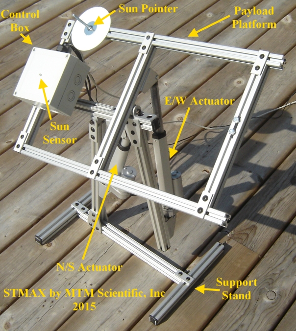
Figure
1. The STMAX Dual Axis Solar Tracker
Instead of using a sensor to find the sun, the apparent position of the
sun in the sky can be calculated based upon the time and
location of the observer. A GPS
module is capable of providing the time and location information.
However, the
actual calculation of the sun's position requires a microcontroller
capable
of performing trigonometric math. The STMAX solar tracker controller
uses a
Picaxe-20X2 microcontroller. The Picaxe-20X2 microcontroller is capable
of
receiving the GPS information and is also capable of calculating the
sun's position. This webpage describes how to acquire the GPS data. We
will be publishing additional webpages to describe the calculations ( Page 2: Calculate the
sun's position ), and also how to move to the correct aiming
position ( Page 3: Aim using MEMS )
using a MEMS gravity sensor module for feedback.
GPS Data
Acquistion
GPS stands for "Global Positioning System". A
network of satellites is in orbit around the earth and the
satellites transmit radio signals which can be used for position
location. These same satellites also transmit the date and time. The
radio signals from the satellites can be received with a compact and
inexpensive stand-alone electronic GPS module. The GPS module receives
the
signals, calculates the time and position, and transmits the data to
the user via a simple RS-232 serial message protocol. The Picaxe-20X2
microcontroller is capable of receiving the serial data stream. ( External
Link: Make a GPS Clock with Picaxe )
In this project we are using the EM-411 GPS module from Globalsat
Technology Corporation. This particular GPS module is a self-contained
device: complete with internal antenna, calculation engine and serial
stream
output... all in a tiny 3cm square package. The EM-411 is
available from www.dx.com ( Datasheet: EM-411.PDF
) The GPS module begins signal acquisition when +5VDC
power is applied. When the GPS signals are correctly received a
red LED on the module begins to flash. The module transmits the
the information as a continuous string of RS-232 messages. The format
of
the text messages is called 'NMEA', which stands for National Marines
Electronics Association. (BTW: An EM-506 GPS module will also work in
this application, however be advised that the RX and TX pins are
reversed!)
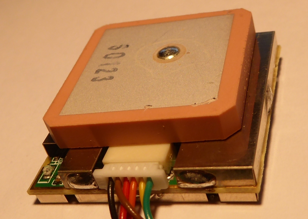
Figure
2. The EM-411 GPS Module
Each message from the GPS module is preceded by a text string
identifier. In this project we are using the text message identified by
the string "$GPRMC". The serial data strings are transmitted at 4800
baud with 8 data bits, no parity and 1 stop bit. (Note: Serial data
protocol is discussed extensively in our book "Build A Solar Tracker".)
The Picaxe-20X2 microcontroller easily receives this
serial data
protocol.
The serial data stream conveys the GPS information as a string of text
data separated by comma delimiters. Our code must receive
the data string, and then parse the information to
extract specific
data for calculating the sun's position. So briefly, the code: 1)
Watches for the text string "$GPRMC", 2) Stores the text data string
after the header is identified, and 3) Parses the data string to
extract
the needed information.
The information we are parsing from the data string is the following:
UTC
Time (Hour & Minute), Position (Latitude-Longitude &
Hemispheres) and Date (Month & Day of Month).
The GPS module begins searching for satellites when +5VDC power is
applied. The time required to establish satellite reception the first
time depends on several factors. In most cases the data stream is
acquired in less than 1 minute. This is sometimes referred to as a
'cold start'. The GPS module transmits the serial
text messages continuously thereafter, so long as DC power is present.
The program to receive the serial data stream is written in a computer
language called "Picaxe Basic". The software language is available free
of charge as part of an IDE (Integrated Development Enviroment) from
Revolution Education, LLC. (http://www.picaxe.co.uk). Once downloaded
and installed, the IDE can be used to view and modify the source code
available here. The IDE is also capable of programming the Picaxe-20X2
IC
by way of a simple serial port connection. (This is described in much
more detail in our book.)
It is a rather simple matter to connect the GPS module to the
Picaxe-20X2. The STMAX circuit board was designed to
include provision for
adding optional features. In this example we have connected the serial
stream data line from the GPS module to Pin C.6 of the Picaxe-20X2 on
the STMAX printed circuit board. Note that you don't need the STMAX
circuit board to
experiment with this code. You can simply work with a breadboard setup
that supplies a Picaxe-20X2 with power and has the basic serial
programming connections shown here, and as described in the Picaxe
manuals.
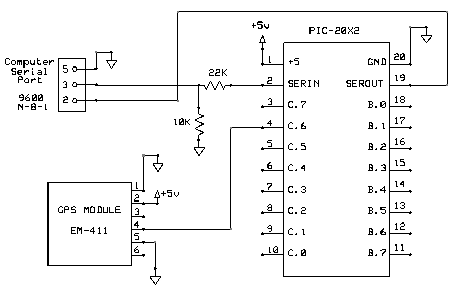 Figure 3. Circuit Diagram
for using the GPS module with the Picaxe
Figure 3. Circuit Diagram
for using the GPS module with the Picaxe
The software source code for the GPS data acquisition includes
numerous comments to explain the general program flow. However, there
are several features of the code which will be given special mention:
The serial GPS text data is a fast stream of information which is
quickly shuttled to memory using the incrementing bit pointer command
after the header is detected. The data stream is afterwards relayed to
the host computer as a simple memory dump of ASCII data. Because the
data is comprised of ASCII symbols, it is necessary to perform an
arithmetic conversion into their true numerical equivalents. The
numerical equivalents are stored in upper memory, so as to free up
lower
memory for other uses. (To be explained in subsequent webpages.) The
parsing routine simply uses the byte locations as the determinant of
data identity. This parsing routine encounters a pitfall though with
the month
and day data near the end, due to a variable-length data element
preceding it. A simple logical parsing branch solves that issue.
Finally, a data integrity check is performed to insure reasonable
information has been acquired. Failure of the data integrity check
forces another string of GPS information to be acquired for subsequent
evaluation.
Having used this GPS module and software code over the course of
several years, we are quite pleased with how reliable it has been in
this application.
If you would like to experiment with this code here is a link to the
complete source code for the entire project: sun_28.bas