MTM Scientific, Inc... PIC Project for CATV Tuner
The CATV Tuner sold by MTM Scientific, Inc can be used for wideband audio and video reception, as described on our other project pages such as the FM Wideband Receiver and Radio Telescope Project. A common requirement in all these projects is the need to program the CATV tuner with a serial bit stream to establish operating frequency. We have previously described a method which uses a computer's parallel port with software, and another method which uses DIP switches with CMOS circuitry. Here we present a 3rd way of programming the tuner by using a PIC microcontroller, more specifically a PICAXE-08M.
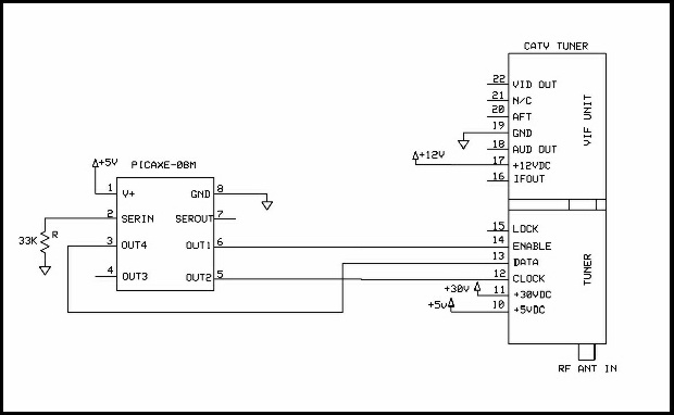
Here is the circuit diagram for connecting the PICAXE chip to the CATV Tuner. The PICAXE-08M chip provides three signals to the tuner: Enable, Data and Clock. The Enable line prepares the tuner to accept a programming signal, the Clock line establishes the communicaton rate, and the Data line is the actual bit data.
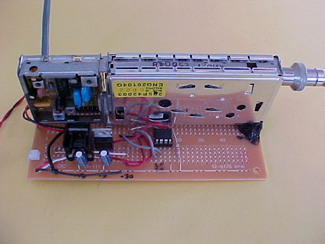
The PICAXE chip must be supplied with a well regulated +5VDC source. Also, the tuner must be supplied with +5VDC, and additionally voltages of +12 VDC and +30 VDC. (In the photo example, two +15 VDC supplies were connected in series to create +30 VDC, and the +5 and +12 voltages were derived using LM05 and LM12 regulators off the lower +15 VDC supply.)
The code for the PICAXE chip is written in a very simple programming language which is specific to the PICAXE controller chips. The source code is listed below in the appendix. As written, this code will tune to UHF channel 37, for doing Radio Astronomy. Of course, the source code can be modified for tuning a different frequency.
The program code is fairly simple and self explanatory. The code generates the clock signal using software, and programs each of 27 bits in the data line to be either ON or OFF. The purpose of the 27 bits is for programming the tuner. Each programming bit has a specific purpose. We have written a short explanation of the programming bits in a tutorial available here: 27 Bit Tutorial
The PICAXE chips are available from fellow hobbyist Phil Anderson. Here is a link to his site: http://www.phanderson.com/picaxe/
The free software for programming the PICAXE chips with the source code (via a serial port connection) is available at this site: http://www.rev-ed.co.uk/picaxe/
Of course, this simple project is only the start of what is possible with the CATV Tuner and a PICAXE chip. Obvious next steps would be to monitor the LOCK signal from the tuner, program the chip to scan frequencies, or even add a numeric keyboard interface and LCD display. If you do happen to develop a good PICAXE based project for the tuner, please forward it to us here at MTM and we will post the details for other experimenters to use.
Appendix:
Here is a listing of the source code for tuning UHF channel 37
symbol n = b1				'define the counter symbol

main:		pause 500		'stabilize power supply 1/2 sec
		low 1			'initialize
		low 2			'initialize
		low 4			'initialize
		pause 500		'stabilize 1/2 sec
		high 1			'raise tuner program enable
		pause 10		'enable stabilize

loop:		for n = 1 to 27		'program tuner with 27 bits
		high 2			'raise clock
		pause 10
					'choose the high bits
		if n = 5 then datah
		if n = 7 then datah
		if n = 11 then datah
		if n = 12 then datah
		if n = 16 then datah
		if n = 20 then datah
		if n = 24 then datah
		if n = 26 then datah


		gosub datal	'all other bits set low

index:	next n			'index n and loop again

		low 4		'exit in a known state
		low 2		'exit in a known state
		low 1		'lower tuner program enable
		pause 10	'enable low stabilize
		end		'end the program

datah:	high 4			'subroutine to transmit high bit
		pause 10
		low 2
		pause 10
		goto index

datal:	low 4			'subroutine to transmit low bit
		pause 10
		low 2
		pause 10
		goto index

				'pin 1 enable, pin 2 clock, pin 4 data
Click Here to View other Products from MTM Scientific, Inc.